Wheel Fender Drawing and Dimensions:
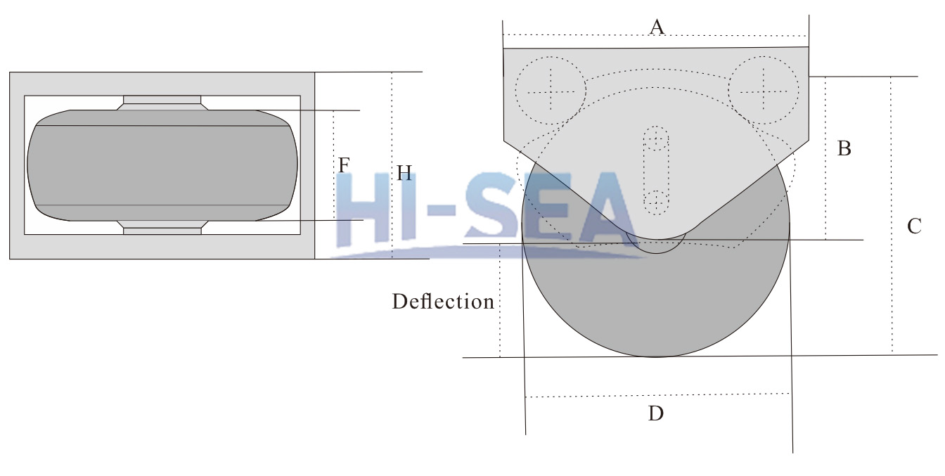
| A |
B |
C |
D |
H |
F |
Deflection |
| 1700 |
1000 |
1450 |
1080 |
900 |
460 |
400 |
| 2000 |
1200 |
1750 |
1300 |
1000 |
510 |
500 |
| 2650 |
1500 |
2200 |
1750 |
1150 |
690 |
600 |
| 2750 |
1750 |
2550 |
1980 |
1250 |
760 |
700 |
| 3350 |
2200 |
3200 |
2550 |
1600 |
970 |
925 |
| 4200 |
2500 |
3750 |
2900 |
1700 |
1020 |
1200 |
|
NOTE (units:mm)
|
The drawing and dimensions are for reference. Other specifications are also available. Please contact us for detailed information.
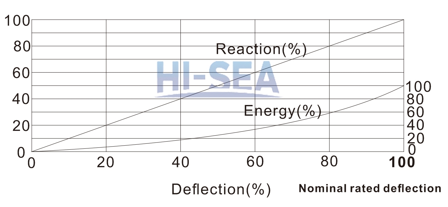
The Performance Curve of Wheel Fender
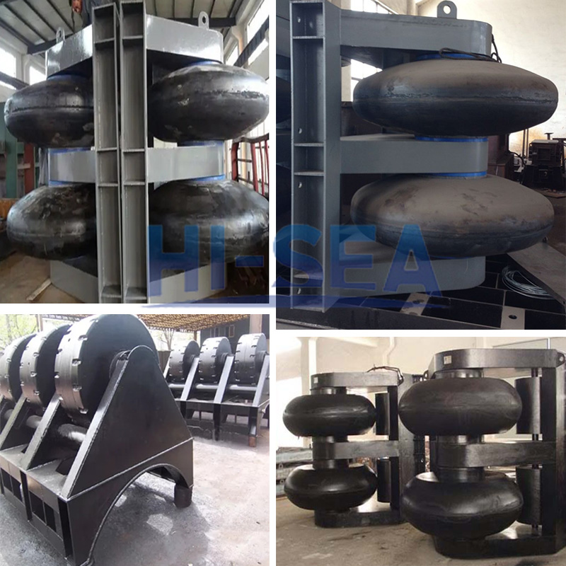
Wheel Fenders in Factory:
wheel fenders and roller fenders have the similar profile. The fenders in the pictures below can also be taken as roller fenders.
Introduction:
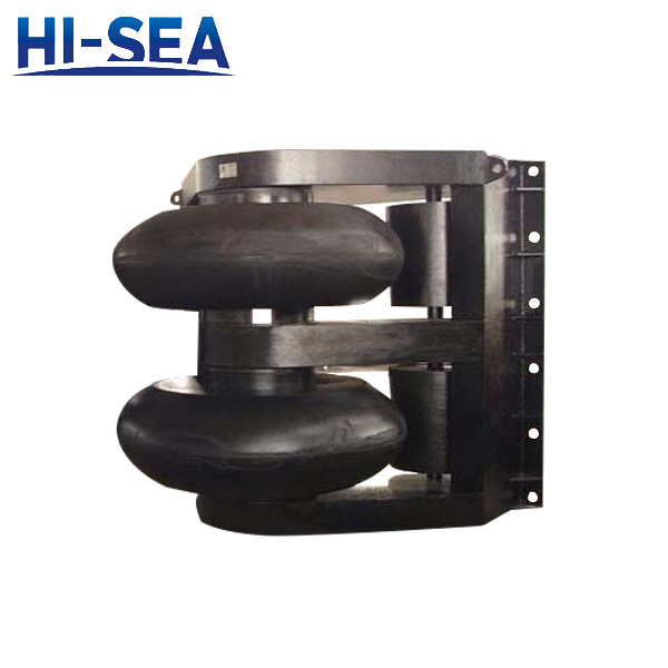
Wheel fender is designed as an energy absorbing elastomer mounted onto a rotating shaft with a frame. The maintenance free bearings are made of steel or composite materials, which are strong and robust. Wheel fender has the same functions and traits as roller fender. Moreover, they even have nearly the same structure. The main purpose of they are designed is to guide ships or vessels to berth in the right direction and lower down potential damages to the vessel hulls and the docks.


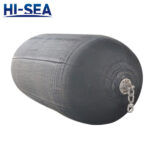 Sling Type Pneumatic Rubber Fenders(4500×12000)